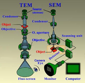
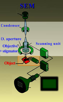
Similarly to light microscopy, in electron microscopes (EM) one finds a source (here an electron gun and not a light source). The large central column holds a number of diaphragms, which restrain the dispersion of the electron beam, and lenses (here no glass lenses but electro-magnetic coils) that deflect electrons. There is a condenser lens which concentrates the beam, and there is an objective lens to focus the beam on the object. In TEM, there is an additional projection lens (beneath the objective lens) to project the image on a screen. In a SEM one can find also components to produce the scan movement of the electron beam. While electrons strike a structure they interact with it and by doing so unravel some of its details (more about the
principle of EM). In order to prevent overheating and spiking inside the column due to collisions between the electrons and gas molecules, the innercompartment of the EM are maintained in a high-vacuum. The object chamber can be reached from outside through an inslide chamber. In SEM this chamber can be found right below the column, but in TEM it is located about half way the column. These positions relate with the specific mode of image formation in either TEM or SEM. Depending whether one wants to apply TEM or SEM techniques, the sample will have to be subjected to distinct preparative procedures (for
TEM or
SEM samples).
Main parts of scanning electron microscopes (SEM)
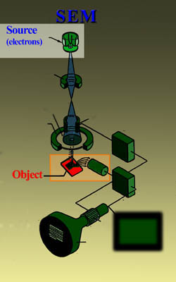
Summarized, the following components are present in an SEM:
- An electron source
- Lenses and coils in the column (a condenser lens, an objective lens, stigmator lenses, coils for the x-y scan movement)
- Object chamber
- Detection device for image formation
1. Source of electrons
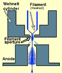
In conventional SEM: In classical electron microscopes electrons are mostly generated by heating a
tungsten filament by means of a current to a temperature of about 2800°C (electron gun). Sometimes electrons are produced by a crystal of lantanumhexaboride (LaB
6) that is mounted on a tungsten filament. This modification results in a higher electron density in the beam and a better resolution than with the conventional device.
In FESEM:
In a field emission (FE) scanning electron microscope no heating but a so-called "cold" source is employed. An extremely thin and sharp tungsten needle (tip diameter 10
-7 -10
-8 m) functions as a cathode in front of a primary and secondary anode. The electrons are accelarated in the direction of the colom by a voltage gradient (see example for a traditional SEM in the table here below). The voltage between cathode and anode is in the order of magnitude of 0.5 to 30 KV. Because the electron beam produced by the FE source is about 1000 times smaller than in a standard microscope, the image quality is markedly better. As field emission necessitates an extreme vacuum (10
-8 Torr) in the column of the microscope, a device is preswent that regurlarly decontaminates the electron source by a current flash. In contrast to a conventional tungsten filament, a FE tip last theoretically for a lifetime, provided the vacuum is maintained stable.
| Source of electrons in a conventional SEM and FESEM |
 |  |
 |
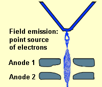 |
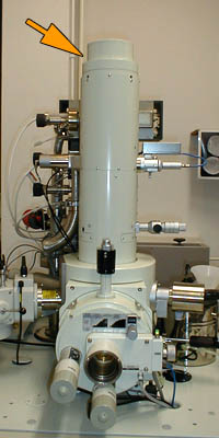
| Part of a (FE)SEM where electrons are generated | Source of electrons in a conventional SEM with thermionic tungsten filament and Wehnelt cylinder (upper illustration)
Minuscule and sharp source which produces electrons in a Field-emission SEM (lowe illustration) |
2. Column
The electron beam is focused by the electro-magnetic lenses (condenser lens, scan coils, stigmator coils and objective lens) and the apertures (diaphragms) in the column to a tiny sharp spot.
- Condenser lens to concentrate the beam
The current in the condenser determines the diameter of the beam: a low current results in a small diameter, a higher current in a larger beam. A narrow beam has the advantage that the resolution is better, but the disadvantage that the signal to noise ratio is worse. The situation is reversed when the beam has a large diameter. The condenser lens consists mostly out of two parts.
- Scan coils
The scan coils deflect the electron beam over the object according to a zig-zag pattern. The formation of the image on the monitor occurs in synchrony with this scan movement. The scan velocity determines the refreshing rate on the screen and the amount of noise in the image (rapid scan = rapid refreshing = low signal = much noise; see SCANMODE in the virtual FESEM). The smaller the scanned region on the object, the larger the magnification becomes at a constant window size (see MAGNIFICATION in the virtual FESEM). Scan coils often consist of upper and lower coils, which prevent the formation of a circular shadow at low magnification.
- The objective lens for the focus
The objective lens is the lowest lens in the column. The objective focuses the electron beam on the object (see FOCUS in the virtual FESEM). At a short working distance (= object in a higher position, that is closer to the objective lens) the objective lens needs to apply a greater force to deflect the electron beam. The shortest working distance produces the smallest beam diameter, the best resolution, but also the poorest depth of field. (The depth of field indicates which range in vertical direction in the object can still be visualized sharply).
- The stigmator coils to obtain a nice round electron beam
The stigmator coils areutilized to correct irregularities in the x and y deflection of the beam and thus to obtain a perfectly round-shaped beam. When the beam is not circular, but ellipsoidal, the image looks blurred and stretched (see ALIGN X Y in the virtual FESEM).
| Column in a SEM |
 |
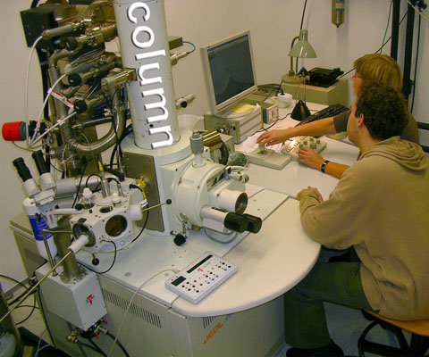 |
| Lenses and diaphragms in the SEM | Column of the cryo-SEM
The column contains electromagnetic lenses and diaphragms. Behind the column, we can see tubing which is connected to the pumps maitaining the high vacuum |
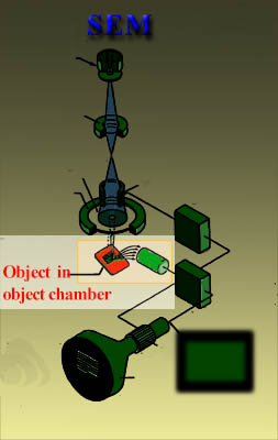
3. Object chamber
The object is first glued to a metal
cylinder and coated with a conductive layer (see
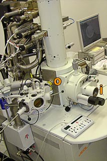
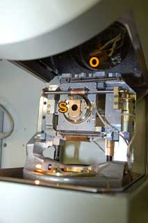
preparation). Then it is mounted on a special holder and inserted through an exchange chamber (indicated by i) into the high vacuum part of the microscope. This is the heart of the microscope where the object chamber (indicated by o) is located: right below the column. From here the object which is clambed to a navigation stage can be repositioned by means of wheels (two black knobs next to the letter i) or with a joy stick that steers along the left-right or forward and backward axes. In addition, the object can be tilted, which is useful to make stereo images (Examples of stereo anaglyph projections of Ambrosia
pollen and of
metal coating from the
PhD thesis of Dr Moret about thin Pb (Zr, Ti)O
3 layers; depth visible with red green stereo glasses)
| Object chamber of the FESEM |
|
|
|
Position of the objectchamber in the FESEM; photo right with opened front panel
o = object chamber, i = entry for the sample, s = stage on which the holder rests |
4. Detection for image formation
In a scanning electron microscope the primary electron beam scans the object in the objectchamber (asterix) according to a line pattern that shifts zig-zagging over the surface. Each point on the surface that is hit by the primary electron beam emits secondary electrons (SE) which contain information on the fine structure of the surface of the sample. This information arises from the number of generated SE at a certain position and the velocity of the SE, which relates to the tilt angle and height of each particular point in the object. Other elctron bounce on the surface of the object. These elctrons are called back-scatter electrons. They provide an indication on the hardness of the material.
| Detection in the FESEM |

|
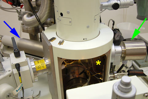 |
Position of electrons in a FESEM
The front unit has been moved to show the inner part of the object chamber (o). The detector for secondary electrons is indicatefd by a green arrow, the one for the back-scattered electron by a blue arrow. |
In the object chamber the SE are attracted by the Corona and strike the "Secundary Emission Detector" that contains a scintillator (fluorescing disk). The more SE reach the scintillator, the more intense the production of photons is (the SE detector is indicated by a green arrow). This luminescence signal is further amplified and transduced to a video signal that is fed to a cathode ray tube in synchrony with the scan movement of the electron beam. The contrast in the 'real time' image that appears on the screen reflects the structure on the surface of the object. Parallely to the analog image, a monochromatic (gray levels) digital image is generated which can be further processed. The back-scatter elctrons are detected in a similar way by another device (the detectorfor back-scatter electron is indicated by the blue arrow).
 Similarly to light microscopy, in electron microscopes (EM) one finds a source (here an electron gun and not a light source). The large central column holds a number of diaphragms, which restrain the dispersion of the electron beam, and lenses (here no glass lenses but electro-magnetic coils) that deflect electrons. There is a condenser lens which concentrates the beam, and there is an objective lens to focus the beam on the object. In TEM, there is an additional projection lens (beneath the objective lens) to project the image on a screen. In a SEM one can find also components to produce the scan movement of the electron beam. While electrons strike a structure they interact with it and by doing so unravel some of its details (more about the principle of EM). In order to prevent overheating and spiking inside the column due to collisions between the electrons and gas molecules, the innercompartment of the EM are maintained in a high-vacuum. The object chamber can be reached from outside through an inslide chamber. In SEM this chamber can be found right below the column, but in TEM it is located about half way the column. These positions relate with the specific mode of image formation in either TEM or SEM. Depending whether one wants to apply TEM or SEM techniques, the sample will have to be subjected to distinct preparative procedures (for TEM or SEM samples).


